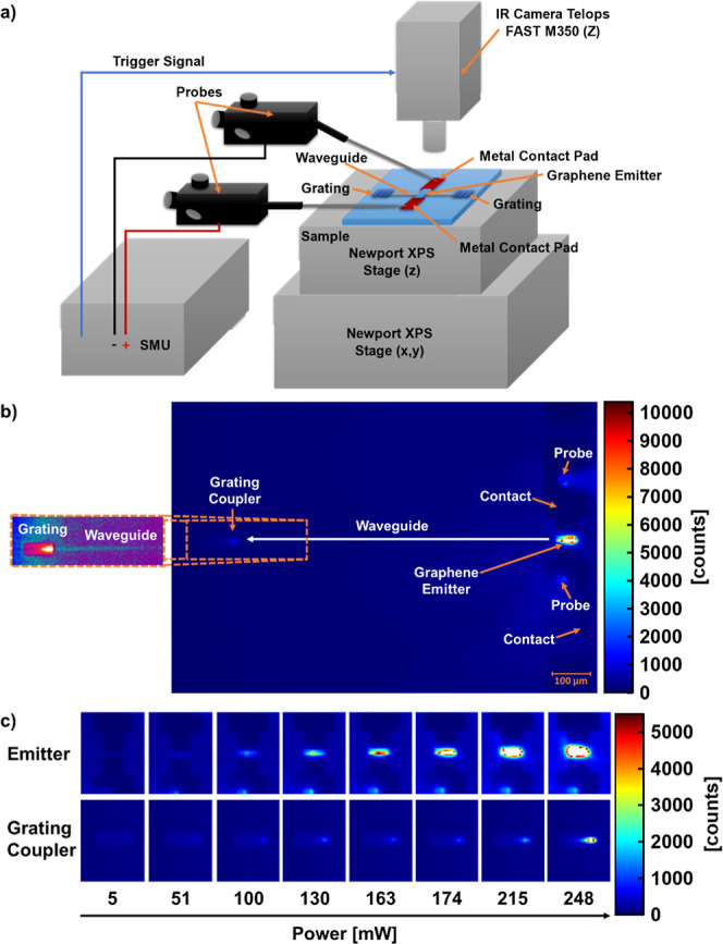
Figure 2.

Mid-IR setup and measurements. (a) Schematic of the mid-IR measurement setup, showing the components and connections to the integrated thermal emitter on the sample. In (b,c) the camera focuses on the emitter and one of the output grating couplers. (b) Mid-IR camera image of a thermal emitter operated at 185 mW. The emitter, contact pads, and probes are visible on the right. The waveguide output grating coupler is visible on the left. The length of the waveguide between the grating coupler and emitter is 725 μm. Inset: Extraction of the output grating with enhanced contrast (using a different color scale), to visualize the radiation pattern of the outcoupled light and the scattering from the waveguide. The scale bar is valid for the entire (b). (c) Mid-IR camera images of the emitter and grating coupler from (b), at different power levels.
