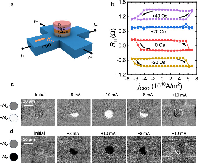
Fig. 4. Current-induced field-free perpendicular magnetization switching.
a Schematic of the Ta/MgO/CoFeB/Ti/CRO Hall bar device for switching measurements and the Ta/MgO/CoFeB/Ti films are etched into pillar with a diameter of 10 μm. b Current-induced magnetization switching of Hall bars device when different in-plane magnetic fields are applied along the direction of the current. The loops are shifted for better visualization and the baseline resistance is about 1.6 Ω. c, d Background-subtracted MOKE images of the Hall bar device during field-free SOT switching. To enhance the contrast, the background in the whole image is subtracted, thus, the whole image in the initial state maintains the same color (gray) though the pillar area is in magnetic polarity state. c MOKE images of the field-free SOT switching magnetization from +Mz state to −Mz state. The positive magnetic field was applied along the +z direction to initialize the magnetization to +Mz state. The gray-colored pillar region represents the +Mz state and white-colored pillar region represents the −Mz state. d MOKE images of the field-free SOT switching magnetization from −Mz state to +Mz state. The negative magnetic field was applied along the −z direction to initialize the magnetization to −Mz. The gray-colored pillar region represents the −Mz state and white-colored pillar region represents the +Mz state.

