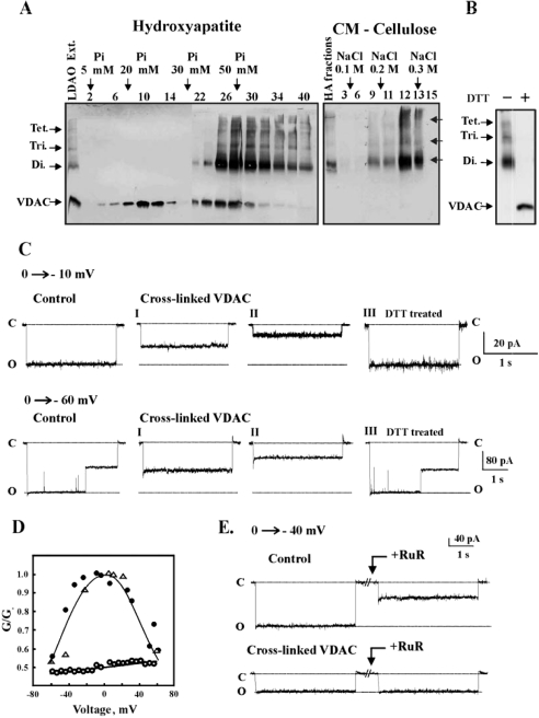
Figure 4. Reconstitution of non-cross-linked and cross-linked VDAC into PLB.
(A) Mitochondria were incubated with the cleavable cross-linking reagent DSP (200 μM) for 30 min at 30 °C and separated from the free reagent by centrifuging at 20000 g. VDAC and its cross-linked products were solubilized with 2% LDAO and purified on hydroxyapatite (HA) column, while cross-linked and non-cross-linked VDAC were eluted with different sodium orthophosphate concentrations. Fractions 32–40 from the HA column were collected and subjected to further separation from residual non-cross-linked VDAC using CM-cellulose. VDAC and its cross-linked products were visualized by immunostaining using anti-VDAC antibodies. Tet., tetramer; Tri., trimer; Di., dimer. (B) Immunostaining of purified cross-linked VDAC-containing adducts before and after preincubation for 30 min at 37 °C with 20 mM DTT. (C) Purified native VDAC, cross-linked VDAC (fraction 14 from the CM-cellulose column, see A) and cross-linked VDAC preincubated with DTT (see B) were reconstituted into PLB. Currents through non-cross-linked VDAC (control) or cross-linked VDAC before (I, II) and after DTT treatment (III) in response to a voltage step from 0 to −10 mV or from 0 to −60 mV were recorded. The broken lines indicate current levels at open (o) or closed (c) states. (D) Multi-channel recordings of the average steady-state conductance of non-cross-linked VDAC (●) and cross-linked VDAC, before (○) and after DTT treatment (△), as a function of voltage. Relative conductance was determined as the ratio of conductance at a given voltage (G) to maximal conductance (Go). (E) Currents through bilayer-reconstituted VDAC or cross-linked VDAC in response to a voltage step from 0 to −40 mV were recorded before and 10 min after the addition of 20 μM RuR. The experiments are representative of 3–4 similar experiments.

