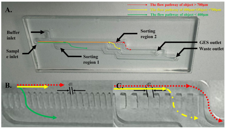
Figure 3.
Images of the microfluidic sorter chip designed for the separation of GESs from other substances based on their size. (A) An image of the entire sorter chip, highlighting the inlets for the buffer and crosslinked GES stream, as well as the outlets for the sorted GESs and waste. (B) A magnified view of Sorting region 1, featuring slots with dimensions of d1 = 400 ± 50 µm, designed to remove objects smaller than 400 µm. (C) A magnified view of Sorting region 2, containing slots measuring d2 = 700 ± 50 µm, intended to collect objects ranging between 400 µm and 700 µm in size. Objects exceeding 700 µm are directed through a 1.2 mm wide microfluidic channel to the waste outlet. The red arrows show the expected route of any object with sizes larger than 700 µm, which leads to the waste outlet. The green arrows show the expected route of smaller objects with sizes of less than 400 µm, going through the slots to the waste outlet. The yellow arrows show the expected route of GESs with a size range of 400–700 µm, going through the slots to the GES outlet and entering the detection chip.

