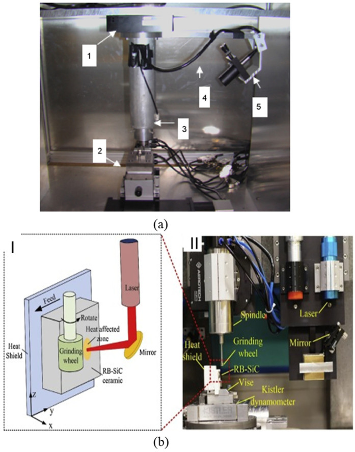
Figure 12.
(a) Laser-assisted milling process experimental setup (1: rotary stage for orienting the laser, 2: stacked linear stages—X, Y and Z, 3: spindle assembly, 4: fibre optic cable, 5: collimator and micrometer assembly); adapted from [105]; (b) Laser-assisted microgrinding (I—schematic diagram; II—Experimental setup); adapted from [106].

