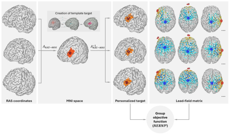
Figure 2.
Target definition and mapping to the individualized brain model of each subject in the Group Optimization database. The central inset (“Creation of template target”) in the MNI space column provides a view of the target specification process. The target consists of a central region (dark red) surrounded by a buffer region of lower weights (in orange). The red rectangle represents the left DLPFC derived from evidence-based TMS targets for depression (59) in combination with the Beam F3 method (60). The MNI coordinates [x,y,z] of the TMS hotspots (1: [−40.6, 41.7, 34.3; −41.5, 41.1, 33.4], 2: [39.3, 46.2 27.5; −41.3, 48.9, 27.7], 3:[−50, 30,36], 4: [−33.6, 30.8, 51.11]) were remapped on the cortex of a default brain model. To obtain the target map in the model, we drew an inner hotspot area encompassing all the mapped points and surrounded it by a buffer area. Group Objective function creation: An individualized transformation is derived by mapping the brain model of each subject from RAS (Right, Anterior, Superior) coordinates into MNI (Montreal Neurological Institute) space. The target map in MNI space is then projected into the brain of each of the database subjects using the inverse transformation (from MNI to RAS coordinates), as described in the main text. The group-objective function (NERNI g, a normalized version of the ERNI described in 22) takes as inputs a weighted target map for each of the subjects. The calculation of the objective function also requires the Lead-field matrix, which is assembled by calculating all possible bipolar calculations with Cz as a common cathode (-1 mA) and the other electrode as an anode (+1 mA), as discussed in 22 (right panel).

