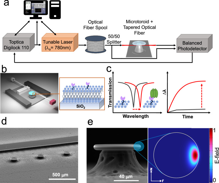
Fig. 1. FLOWER system.
a A tunable laser is coupled to the microtoroid cavity through a tapered optical fiber. b Schematic diagram of the constructed biosensing chamber (top cover glass not shown). The tapered fiber is glued to the support wall with a polymer adhesive. Inset shows the structure of a membrane protein (pink) incorporated in a lipid bilayer (blue) on the toroid’s glass surface. c Sketches of how the resonant wavelength red-shifts when analytes adsorb onto the functionalized toroid surface (inset). d SEM image of microtoroid array alongside a support wall. The scale bar is 500 µm. e SEM side view image of a microtoroid structure. The scale bar is 40 µm. The inset picture shows a COMSOL simulation of an optical mode of the lipid coated cavity in a buffered aqueous solution.

