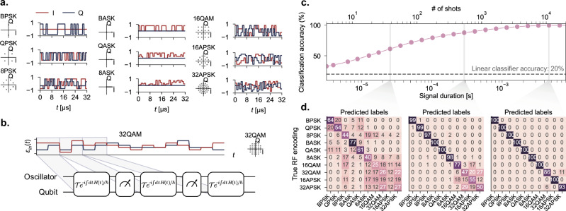
Fig. 3. Classification of radio-frequency (RF) communication modulation protocols.
a Description of the dataset for digital modulation schemes used in this experiment. In conventional digital modulation schemes, one encodes data in the amplitude and phase of the signal. The modulation schemes can be represented by a “constellation diagram” in (I, Q) space (left), where point represents one of the possible choice of (I, Q) values to encode a symbol, with example time traces (right). b These signals are broken up and fed into our reservoir. c The performance of the reservoir as a function of the shots taken in real time (see text). The top row contains the corresponding duration of the radio frequency signal required. As the number of shots increases, the fluctuations in the measurement distribution reduces, resulting in a higher classification accuracy. For context, a classical linear classifier applied directly on the input data achieves only 20% accuracy, independent of the duration of the signal. The error bars of the accuracy curve have been omitted here due to the fact they are too small. d Confusion matrix for the QRC at 32, 512, and 104 shots, showing that the reservoir confuses only a few classes at the highest shots.

