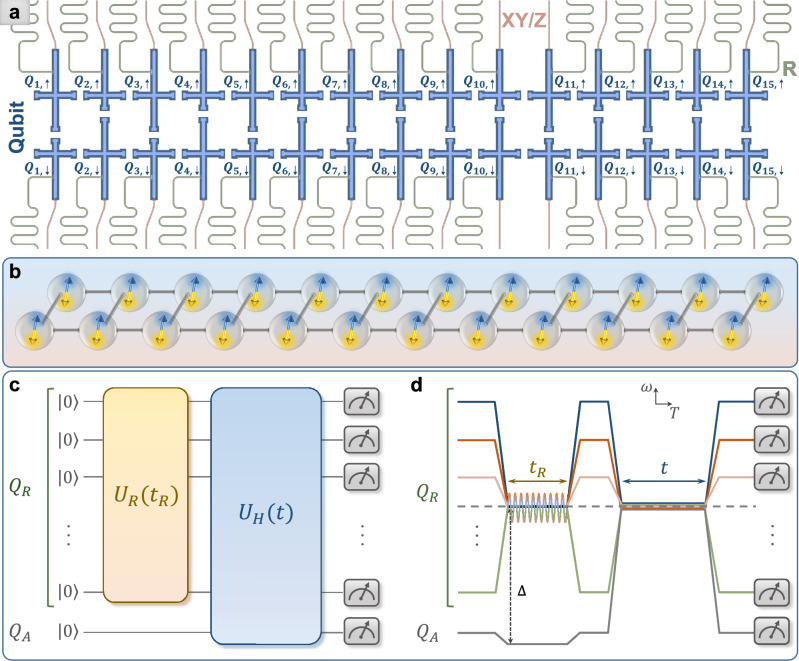
Fig. 1. Superconducting quantum simulator and experimental pulse sequences.
a The schematic showing the ladder-type superconducting quantum simulator, consisting of 30 qubits (the blue region), labeled Q1,↑ to Q15,↑, and Q1,↓ to Q15,↓. Each qubit is coupled to a separate readout resonator (the green region), and has an individual control line (the red region) for both the XY and Z controls. b Schematic diagram of the simulated 24 spins coupled in a ladder. The blue and yellow double arrows represent the infinite-temperature spin hydrodynamics without preference for spin orientations. c Schematic diagram of the quantum circuit for measuring the autocorrelation functions at infinite temperature. All qubits are initialized at the state . Subsequently, an analog quantum circuit acts on the set of qubits QR to generate Haar-random states. This is followed by a time evolution of all qubits, i.e., with being the Hamiltonian of the system, in which the properties of spin transport are of our interest. d Experimental pulse sequences corresponding to the quantum circuit in (c) displayed in the frequency (ω) versus time (T) domain. To realize , qubits in the set QR are tuned to the working point (dashed horizontal line) via Z pulses, and simultaneously, the resonant microwave pulses represented as the sinusoidal line are applied to QR through the XY control lines. Meanwhile, the qubit QA is detuned from the working point with a large value of the frequency gap Δ. To realize the subsequent evolution with the Hamiltonian (1), all qubits are tuned to the working point.

