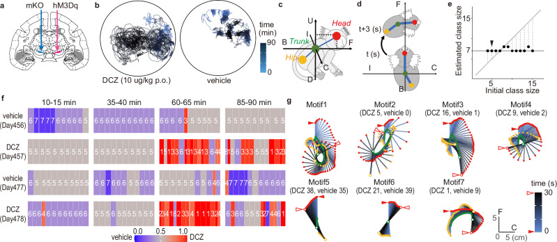
Fig. 5. SMP characterized contralateral rotation behavior induced by chemogenetic manipulation.
a Illustration of viral vector injection locations adapted from Mimura et al.9. AAV vectors expressing excitatory DREADD hM3Dq were injected into the unilateral substantia nigra (SN, red arrow). As a control, an AAV vector expressing a fluorescent marker (mKO) was injected into the contralateral SN (blue arrow). b Example of the top view of the Head trajectory of the marmoset after deschloroclozapine (DCZ; 10 μg/kg, per os (p.o.)) and vehicle administration. c Illustration of the posture coordinate. The horizontal mapping of the Head through the center of the Trunk was defined as the front-back (F-B) axis, and the axes orthogonal to the F-B axis horizontally and vertically were defined as the ipsilateral-contralateral (I-C) and vertical up-down (U-D) axes, respectively. d Body coordinates were used to determine relative positions every 3 s. e Estimation result of motion-motif class size. SMP was applied to four 5-min time windows each from two 90-min sessions after DCZ and vehicle p.o. The result was 7 kinds of motion motifs. f Example of a motion-motif sequence detected by SMP with initial class size = 5 (arrowhead in (e)). The time at which the motif was observed is indicated by tiles and color-coded by the percentage of occurrences in the DCZ data. The days since vector injection are shown below the dosing conditions. g The top view illustration of the body trajectories is represented by the motion motifs in (f). Observed numbers in the DCZ and vehicle groups are under the motif numbers. The red and white arrowheads indicate the starting and ending points of the Head track, respectively. The Head, Trunk, and Hip positions are color-corded as (c), with white at the ending points. The body positions are drawn at 0.5-s intervals with a gradation from blue to black from start to end (see also Supplementary Movie 4).

