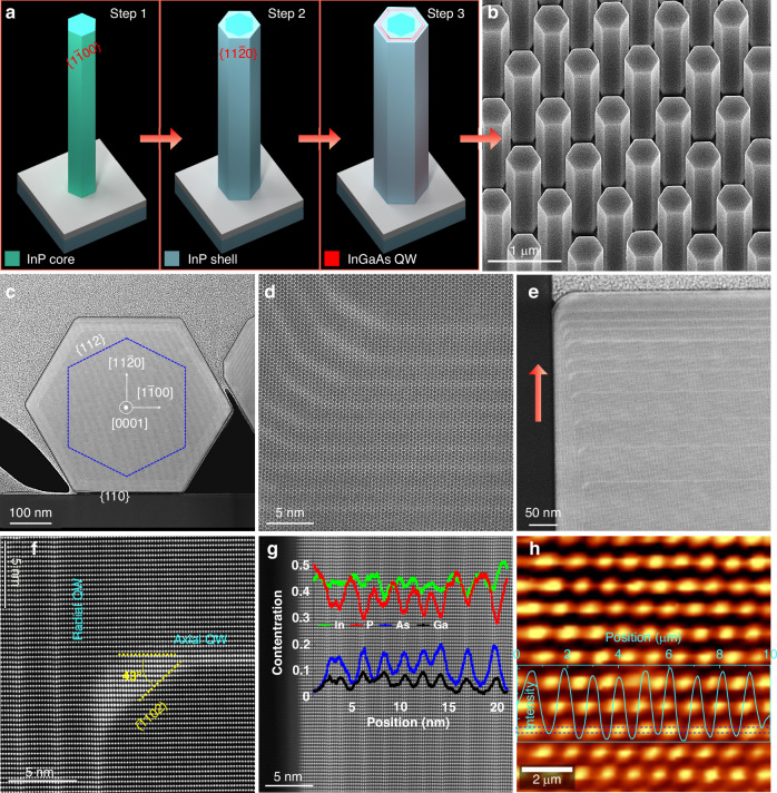
Fig. 1. Structural and optical characterization of the MQW NW array.
a Schematics of the WZ based InP NW, facet-rotated InP core–shell NW, and InGaAs/InP MQW NW, respectively. b 30° tilted SEM image of the NW array grown on InP(111)A substrate. c, d STEM-HAADF image of the lateral cross-section of an InGaAs/InP QW NW at different magnifications. The dashed blue line in (c) indicates the expected position of WZ InP NW core which is covered with the 30° rotated InP shell and MQW structure. e–g STEM-HAADF image taken along [112] zone axis from the vertical cross-section of NW top segment. The pink arrow in (e) indicates the NW growth along the (111)A direction. Line scan of EDX intensity along the radial QWs are superimposed in (g). h PL intensity map of the NW array with the intensity line scan from the region within the blue dashed lines showing uniform optical emission from the array

