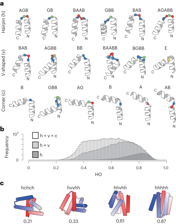
Fig. 3. 18 HLH tertiary motifs and generated α-helical backbone structures.

a, Identified 18 HLH tertiary motifs typically observed in nature. The motifs are classified based on the bending angle between the two helices in the motifs: hairpin (h), v-shaped (v) and corner (c), which are presented in order of the magnitude of the bending angle, with the ABEGO backbone torsion pattern for the connecting loop. The residues with the backbone torsion angle, A, B, E and G, in the ABEGO torsion representation (‘A’ corresponds to the right-handed α-helix region in the Ramachandran map, ‘B’ to the β-strand region, ‘E’ to the extended region with a positive phi angle, and ‘G’ to a left-handed α-helix) are shown in red, blue, yellow and green, respectively. b, HO distributions for generated backbone structures with six helices. The black, gray and white bars respectively represent the distributions for the ensemble generated using only hairpin motifs (h), hairpin and v-shaped (h + v) motifs, and all three motifs (h + v + c). Incorporation of v-shaped and corner loops yields lower HO structures. c, Examples for the generated backbone structures. The used motif type strings and the HO values are indicated for each structure. The N- and C-terminals are colored in blue and red, respectively.
