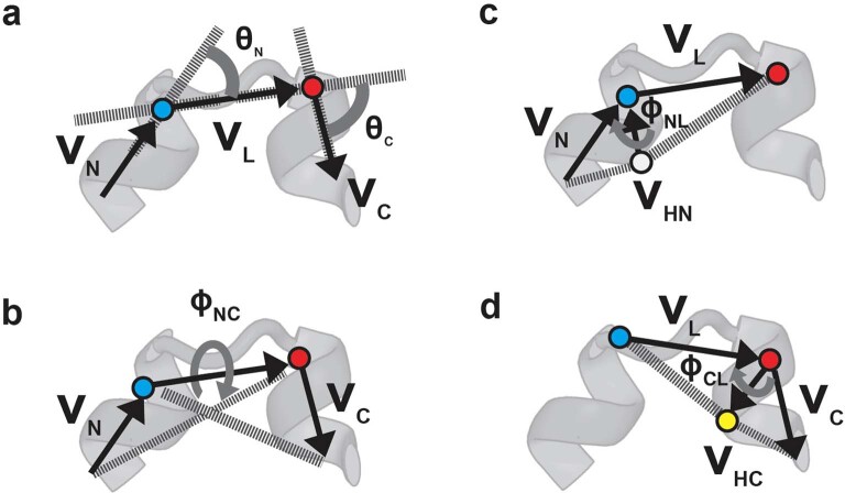
Extended Data Fig. 2. The five features representing the HLH tertiary geometry.
a-d, For representing tertiary geometries of HLH units, the following angles, θN, θC, ϕNC, ϕNL, and ϕCL, were identified using the VN, VC, VL, VHN, and VHC vectors (these vectors are calculated using Cα atoms). a, The definitions of θN and θC. VN and VC respectively represent the helix vectors for the N- and C- terminal helices in a HLH geometry, which are calculated using the equations proposed by Krissinel et al.53. VL is the loop vector from the last Cα atom (blue) in the N-terminal helix to the first Cα atom (red) in the C-terminal helix. θΝ was identified as the angle between the VN and VL vectors; θC, was identified as the angle between the VC and VL vectors. b, The definitions of ϕNC· ϕNC was identified as the dihedral angle between the plane defined with the VN and VL vectors and that with the VC and VL vectors. c, The definition of ϕNL· VHN is the helix spiral vector at the end of the N-terminal helix, which was identified as the vector pointed to the last Cα atom (blue) in the N-terminal helix from the Cα atom immediately before the last Cα atom (white). ϕNL was identified as the dihedral angle between the plane defined with the VHN and VL vectors and that with the VHN and VN vectors. d, The definition of ϕCL· VHC is the helix spiral vector at the beginning of the C-terminal helix, which was identified as the vector from the first Cα atom (red) in the C-terminal helix to the Cα atom immediately after the first Cα atom (yellow). ϕCL was identified as the dihedral angle between the plane defined with the VC and VHC vectors and that with the VL and VHC vectors.

