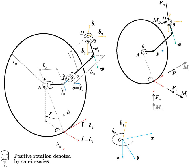
Fig 2. Kinematic and free body diagram of a modified castor wheel.
Left: Kinematic diagram. Point D is the connection to the vehicle, point A is the connection between the castor fork and wheel, and C is the geometric contact point. The castor fork extends down from connection point D with length Lw. The longitudinal castor trail Lf1 is the minimal length of the castor fork between the swivel axis and the wheel spin axis . A lateral trail Ls is defined along the wheel spin axis . Rotations are visualized using a cans-in-series [13] representation, where the positive rotation direction is indicated with an arrow. The wheel bank angle σ is illustrated using cans but is a solid connection. The rake angle φy is not shown for simplicity. A case equivalent to moving forward with a rake angle occurs if a castor wheel with a cant angle is moved in the direction. Right: Free body diagram of the castor wheel. The force and moment on point D act on the vehicle, and the contact forces and moments at point C act on the ground. Moments that are assumed negligible in the model are colored gray.

