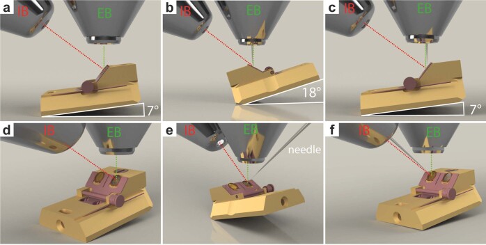
Extended Data Fig. 3. Stage orientations for Serial Lift-Out with a 45° pre−tilted shuttle.
a, d, Copper block preparation and trench milling are performed at 7° tilt angle and 180° relative stage rotation (trench milling orientation) b,e, Lift-out of the copper block is performed at 18° tilt angle and 0° relative rotation (lamella milling orientation). The same orientation is used during the attachment of Serial Lift-Out slices to the receiver grid and lamella thinning. c,f, Lift-out to obtain sections perpendicular to the grid plane is performed at trench milling orientation. Panels d-f are oblique front views of the corresponding side views shown in a-c. From this perspective, the HPF sample is located in the left shuttle position and the receiver grid is located the right shuttle position. Panels b,c,e,f show the EasyLift-needle inserted. EB and IB indicate the column of the ion beam and electron beam, respectively.

