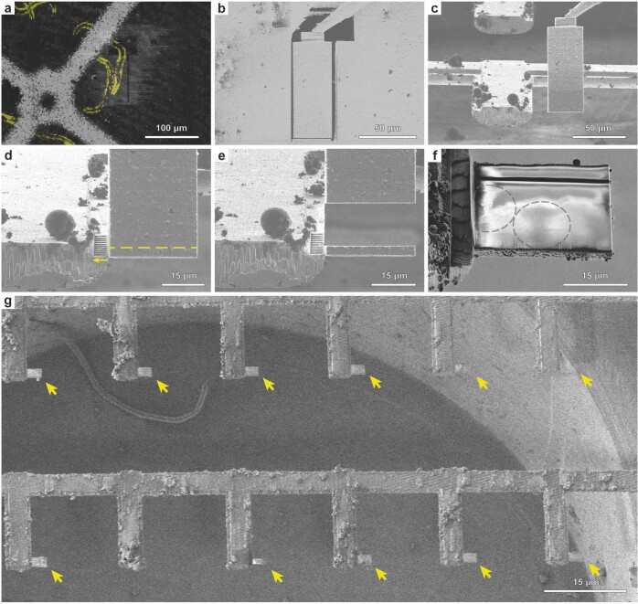
Extended Data Fig. 4. A workflow for single−sided attachment Serial Lift-Out.
a, FIB image of the extraction site with overlaid correlated fluorescence data (yellow) indicating the larva being targeted (trench milling orientation). b, The extraction volume is attached to the EasyLift needle using redeposition from the copper adapter. The release cut, milled with a line patten, is noticeable at the base of the extraction volume (trench milling orientation). c, FIB image of the extracted volume being lowered to the attachment position adjacent to a pin. For attachment, the lower front edge of the volume is aligned to the corner of the pin. d, Attachment using redeposition from the pin (yellow arrow indicates milling direction), followed by line pattern milling releasing the section of a desired thickness (dashed yellow line). e, The resulting section is depicted as the remaining extracted volume is retracted. f, SEM image of a typical section after release from the extraction volume. Note the faint pattern of worm cross-sections discernible (grey dashed lines). g, SEM image of the resulting receiver grid after a session of single−sided attachment Serial Lift-Out. Arrows indicate the 12 sections obtained. Supplementary Movie 2 summarizes the process.

