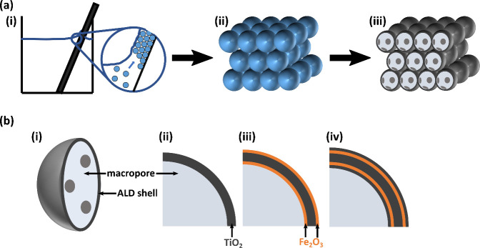
Figure 1.
Schematic drawing of the fabrication of TiO2–Fe2O3 IOs and their shell composition. (a) Different steps in the fabrication process show (i) self-assembly of PS spheres, (ii) an assembled PS sphere opal template, and (iii) a TiO2 inverse opal after ALD coating and burn-out of the polymer template. The latter scheme presents cuts through the front row of spheres to visualize the hollow inside and gaps connecting neighboring macropores. (b) The TiO2 IO structure presented in (i) and (ii) is further modified by ALD functionalization to produce (iii) TiO2–Fe2O3 bilayer IOs and (iv) TiO2–Fe2O3–TiO2 multilayer IOs.

