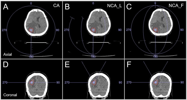
Figure 1. Three different arc arrangements compared.
The images show head computed tomography (CT) images of a patient harboring a single brain metastasis (BM) in the right parietal lobe (A-F); the location of a gross tumor volume (GTV), the irradiation isocenter position, and three arc arrangement patterns (A, D; B, E; C, F); axial views (A-C); and coronal views (D-F).
The three arc arrangements consist of two coplanar arcs (CAs) alone with to-and-fro rotations of 360º and each collimator angle of 0 and 90º (A, D); one coplanar arc (CA) and two non-coplanar arcs (NCAs) with each arc rotation of 120º to minimize the beam path lengths and the collimator angle setting of 0, 45, and 90º (B, E); and one CA with 360º rotation and the collimator angle of 0º and two NCAs with each 180º rotation and the collimator angles of 45 and 90º (C, F). The couch was rotated 60º clockwise and counterclockwise so that NCAs trisected the cephalad hemisphere (B, C, E, F).
CA: coplanar arcs; NCA_L: non-coplanar arcs with limited rotations; NCA_F: non-coplanar arcs with full rotations.

