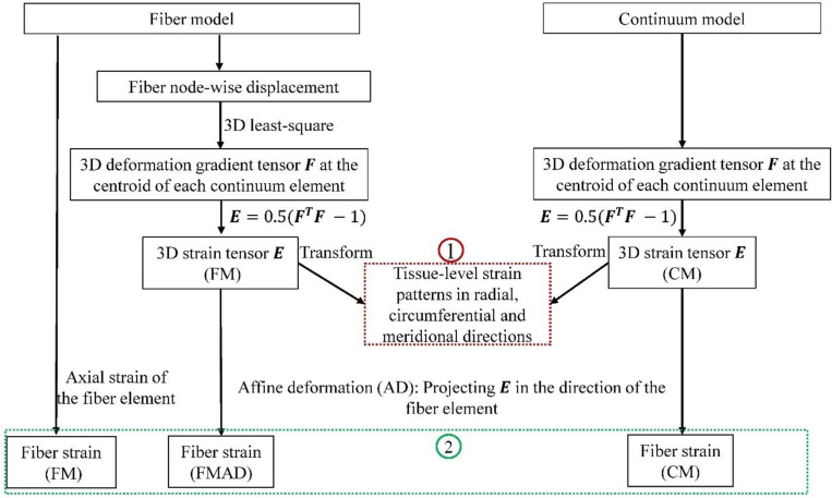
Figure 5.
A flowchart showing the procedures in deriving 3D tissue-level strains (1) and fiber strains (2) for the fiber (FM) and continuum (CM) models. The deformation gradient tensor in the CM was acquired directly from the simulation. For the FM, was also calculated at the centroids of continuum elements to ensure consistent comparisons. The details of this calculation can be found in section 2.3.1. Tissue-level strains in radial, circumferential and meridional directions were computed by transforming the strain tensor from Cartesian coordinates to spherical coordinates, with further details on this transformation and direction conventions available in Section 2.3.1. In the FM, fiber strain refers to the axial strain of the fiber element, derived directly from simulation results. For the CM, fiber strain was determined by projecting the 3D strain tensor along the fiber element direction, following the affine deformation (AD) assumption commonly used in continuum kinematics [35]. This approach relies on the affine deformation (AD) assumption in the continuum kinematics. Employing the same AD assumption, fiber strain was also calculated based on the strain tensor derived from FM, and we refer this as the fiber strain for the fiber model with affine deformation (FMAD).

