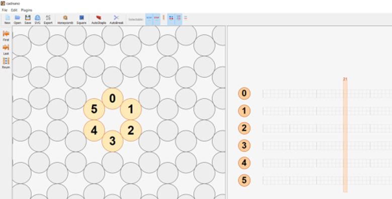
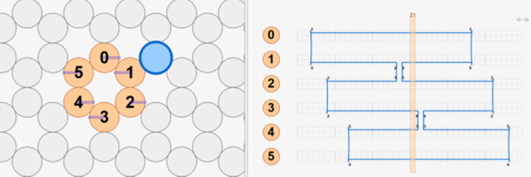
Fig. 13. (A-D) CAD images corresponding to step h. (A) Lattice selection determining staking of helices when looking down the z axis. (B) Selection of helices to populate into CAD file. (C) Populated helices for a six-helix bundle. (D) Automatic scaffold routing created by dragging mouse across helices in C.
| A |

|
| B |

|
| C |

|
| D |

|
