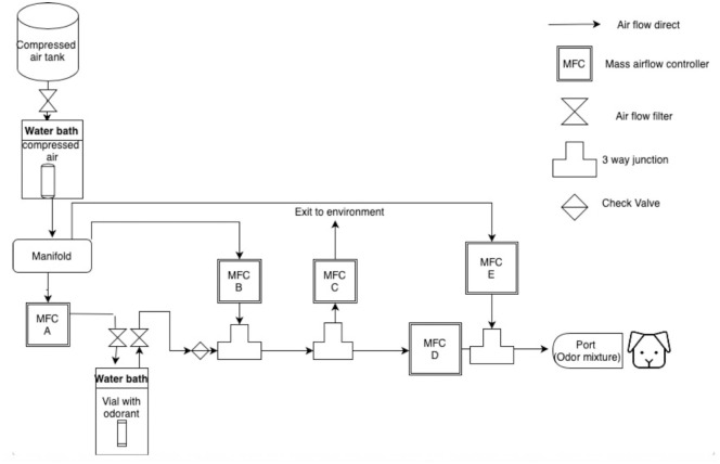
Fig 2. Diagram of mass air flow dilution olfactometer.
The path of air flow is shown from left to right. Clean air travels through a warm water bath heated to replicate the same temperature of the odorant water bath. The clean air then travels to the manifold and is dispersed to the MFC A, MFC B and MFC E. Air from MFC A is pushed into the vial containing an odorant located in a separate water bath to collect the headspace from the vial and then pushed out of the vial to a three-way junction connected to MFC B. The air from the vial is mixed with clean air from the manifold the travels to the remaining mass air flow controllers. The odorant is systematically diluted by the mass air flow controllers and then pushed down the odor line to be delivered to the port.

