. 2024 Sep 4;24(20):4679–4716. doi: 10.1039/d4lc00380b

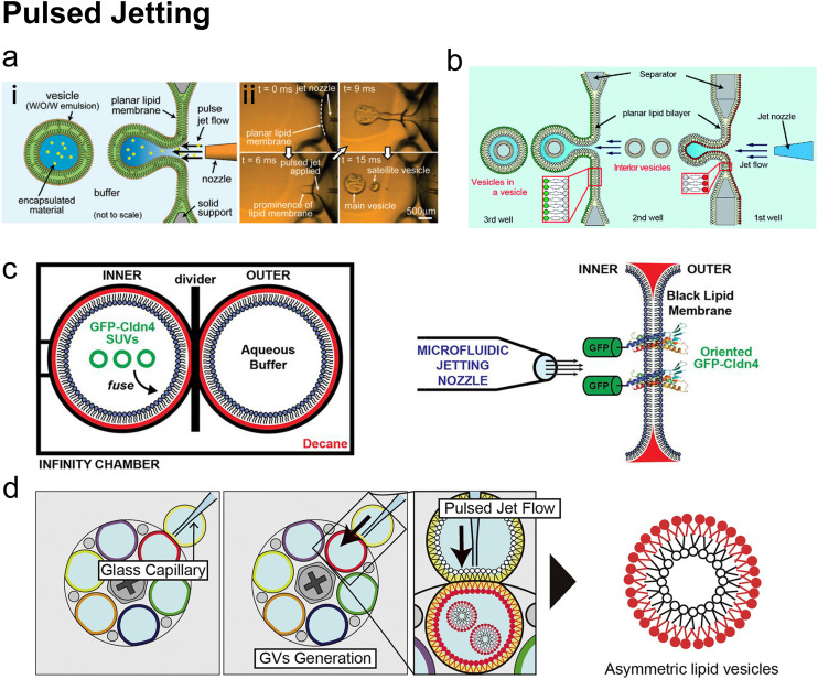
Fig. 13. Pulsed jetting. a| (i) Conceptual diagram of the pulsed jetting method. The green area represents organic solvent. (ii) Sequential images of vesicle formation captured by a high-speed CCD camera. Reproduced from ref. 46 with permission from the American Chemical Society, copyright [2007]. b| Illustration of a mimic exocytosis system of cell-sized lipid vesicle containing small vesicles using a triple-well device. Reproduced from ref. 192 with permission from the Royal Society of Chemistry, copyright [2019]. c| Left: Two-droplet chamber configuration. SUVs delivered GFP-Cldn4 onto the lipid membrane by fusion. Right: Pulsed jetting based on lipid membrane with GFP-Cldn4 on it. Reproduced from ref. 193 with permission from Biologists, copyright [2019]. d| Schematic images of sequential asymmetric GV generation with various lipid combinations. Various asymmetric GVs could be fabricated by aligning the single outer well to inter wells containing different lipid compositions and the conducting pulsed jetting. Reproduced from ref. 194 with permission from Elsevier, copyright [2018].

Fig. 13