. 2024 Sep 4;24(20):4679–4716. doi: 10.1039/d4lc00380b

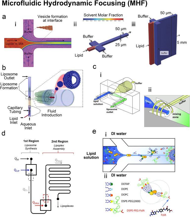
Fig. 4. Microfluidic hydrodynamic focusing. a| (i) Schematic of liposome formation through microfluidic hydrodynamic focusing. Two aqueous streams focus one lipid organic stream. Reproduced from ref. 68 with permission from the American Chemical Society, copyright [2004]. Numerical simulations comparing ethanol concentration profiles within MHF (ii) and VFF (iii) systems. In the VFF system (not to scale), its microchannel aspect ratio is 1000 : 1, much larger than 0.5 : 1 in the conventional MHF system. Reproduced from ref. 71 with permission from John Wiley and Sons, copyright [2015]. b| Schematic of capillary focusing liposome formation device (not to scale). A lipid alcohol solution is continuously injected into the intra-annular capillary tubing and hydrodynamically focused in three dimensions by an exterior sheath flow of aqueous buffer from a surrounding glass multi-capillary array. Reproduced from ref. 72 with permission from the Royal Society of Chemistry, copyright [2014]. c| Microfluidic vortex focusing (MVF) device design and operation. (i) The MVF device design consists of two inlets conjoining at the annular junction, a conical mixing region, and an outlet. (ii) Magnified view on the annular junction. Mixing is improved through vortex focusing. Reproduced from ref. 73 with permission from Springer Nature, copyright [2022]. d| Schematic representation of the microfluidic devices for a two-stage formation of cationic liposome at the 1st MHF region and pDNA loaded lipoplexes at the 2nd MHF region. Reproduced from ref. 74 with permission from Elsevier, copyright [2017]. e| The assembly (i) and structure (ii) of mNALPs in a microfluidic T-junction chip. Mixing of lipid solution and DI water at the nanolitre scale in microfluidic channels leads to rapid changes in solvent properties that drive particle formation. Reproduced from ref. 75 with permission from the Royal Society of Chemistry, copyright [2017].

Fig. 4