FIG. 3.
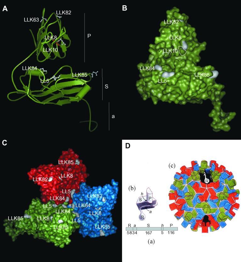
Locations of mutated amino acids on the CNV CP subunit and trimer in CNV transmission mutants. (A) Ribbon diagram of the homology modeled CNV CP subunit (subunit C) showing locations of mutated sites (in white in ball-and-stick form) in each of the transmission mutants. The mutated site in LLK10 is shown in red to distinguish it from the adjacent LLK8 mutation. Locations of the P, S, and a domains are indicated (see panel D for details). The disordered R domain is not shown. (B) Surface representation of the CNV CP subunit (subunit C) showing locations of mutated sites in white. The position of the buried LLK10 mutation is indicated by the white dotted lines. The LLK63 mutation is not visible in this orientation. (C) Surface representation of the CNV trimer (asymmetric unit) showing locations of mutated sites in each transmission mutant. The red, blue, and green areas correspond to the A, B, and C subunits. The asterisk shows the quasi-threefold axis of symmetry (D). (D) Diagrammatic representation of the structure of TBSV used for reference to the CNV structure. (a) Linear order of the different CP domains is shown along with the number of amino acids comprising each CNV domain (R, RNA binding domain; a, arm; S, shell domain; h, hinge; P, protruding domain). (b) Subunit structure with locations of indicated domains. (c) Particle structure with the A subunit in red, B in blue, and C in green. The cutaway section shows the region that the disordered R domain may occupy in the particle interior. (This diagram was adapted from reference 3).

