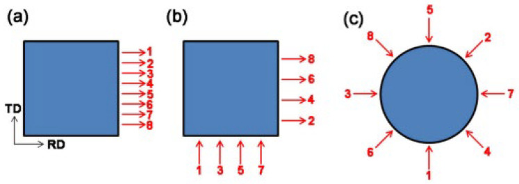
Figure 6.
Schematic diagrams of UNR (a), CRR (b) and CLR (c); 1–8 for the same rolling direction in UNR; 1–8 for the rolling direction of clockwise rotated 90° and 270° alternately in CRR; 1–8 for the rolling direction of clockwise rotated 135° in CLR [165].

