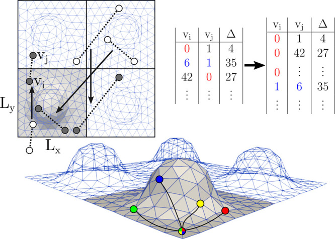
Figure 2.

Illustration of the main steps of calculating the geodetic Mean Square Displacements. After surface meshing, all particle displacements, that is, initial and final particle positions (white circles) separated by a lag time, Δ, are mapped onto the surface, ensuring that both the starting and end points are on the mesh, as close to the origin as possible (gray circles). The resulting (vi, vj) pairs of mesh vertices are written to a binary file along with the corresponding lag time, Δ. For efficiency, all pairs are ordered so that the lower vertex index appears first (see for example the numbers highlighted in blue) and subsequently ordered along the first column, so that all particle displacements involving a given vi appear as a single contiguous block. Finally, the VTP algorithm needs to be called on each source vertex vi only once to evaluate all of the distances in the block. These evaluations are independent and therefore readily parallelized, as done in the current implementation. The computed displacements are assigned to both vertices while also taking account of the associated lag time.
