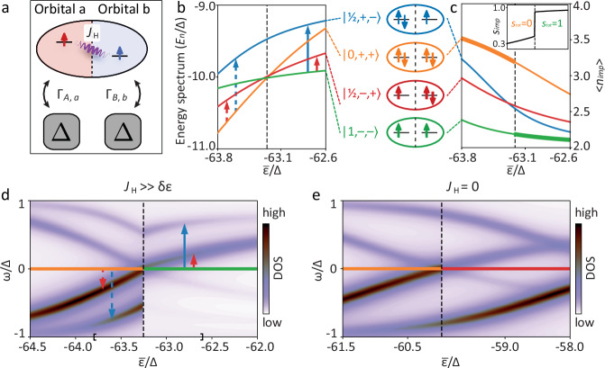
Fig. 3. Theoretical description of a multi-channel QPT.
a Sketch of the model Hamiltonian. The ellipse represents an impurity with two orbitals interacting via a Hund’s coupling JH, while squares represent the two scattering channels of the superconductor coupled to the orbitals, each channel modeled by a superconducting site. b Evolution of the energy of the four lowest-lying many-body states for increasing average orbital energy driven by the STM tip electric field. The vertical arrows indicate the STM-accessible excitations before and after the MCQPT. All the energy curves were shifted by to improve readability. c Evolution of the average total electron occupation on the impurity for all four many-body states (same coloring as in panel b). The thick line marks the ground state for the given value of . The inset shows the spin of the impurity simp and the total spin stot of the ground state in the same range. d Simulated in-gap LDOS at the impurity site as a function of . Vertical arrows same as panel b, where now the direction marks the dominant electron- or hole-nature. The region of shown in b and c is delimited by the square brackets on the horizontal axis. e Simulated in-gap LDOS for the transition in case of absence of Hund’s coupling, JH = 0. The color-coding of the horizontal line at ω = 0 in panels (d, e) represents the ground state (colors from panels b, c). The vertical dashed lines in panels b-e mark the quantum phase transition. Calculation parameters in (b, c, d): JH = 30Δ, U = 60Δ, ΓA,a = ΓB,b = 5Δ2, δε = −6Δ. Same for panel e except JH = 0 and δε = −3Δ. Phenomenological broadening in (d, e) is η = 0.075Δ. Source data for panels d and e are provided as a Source Data file.

