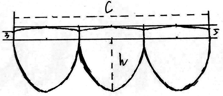
Figure 1.
This figure presents a schematic diagram illustrating the design of the valve leaflets. The free edge of each leaflet is aligned in a straight line, while the bottom edge of the valvular sinus forms an appropriate arc. Each leaflet is of equal length, with their combined length equaling the conduit's circumference (c=π × d). The leaflet height is set at 4/5 of the conduit's diameter (h = 0.8 × d). The bottom margin of the valvular sinus is a symmetrical arc, with the central and free margin heights being 3 mm and 5 mm, respectively.

