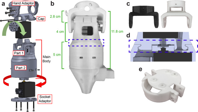
Fig. 1.
Design of the Utah wrist. a Exploded view of the Utah wrist. The red and green arrows correspond to the motors associated with pronation/supination and flexion/extension (or ulnar/radial deviation), respectively. b Photo and dimensions of the assembled wrist with the attachments to connect to a bypass socket. c The wrist can adapt to various terminal devices by printing a new interface part such as the two shown here. d Expanded view of the rotary joint mechanism, as highlighted in part b. e The wrist can connect to various sockets by printing a new interface part, such as the one shown here.

