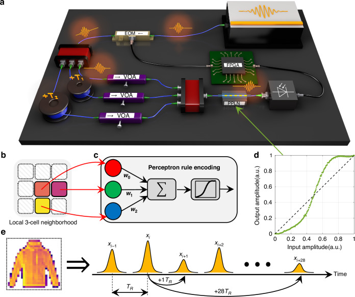
Fig. 2. Experimental setup for PNCA.
a Schematic of the experimental setup. Pulses of light produced by a modelocked laser pass through an electro-optic modulator (EOM) and are split into optical fiber delay lines (blue lines) with relative delays T1 and T2. Linear dot product weights are programmed by tuning the variable optical attenuator (VOA) in each delay line. Nonlinear activation using a periodically-poled lithium niobate (PPLN) waveguide is performed following the coherent interference of light pulses, with the resultant amplitudes stored on a field-programmable gate array (FPGA) and reinjected (black lines) to drive the input EOM for the next iteration. b Local 3-cell neighborhood enforced by relative delays T1 and T2. c The local update rule is encoded by a single perceptron with 3 programmable parameters. d PPLN nonlinear activation function. e Cells representing pixels of an image are encoded by the amplitude of light pulses with repetition period TR in a synthetic temporal dimension. For example, pulses can be coupled using optical delay lines with T1 = +1TR and T2 = +28TR to implement the local 3-cell neighborhood shown in (b) for fashion-MNIST images

