Figure 9.
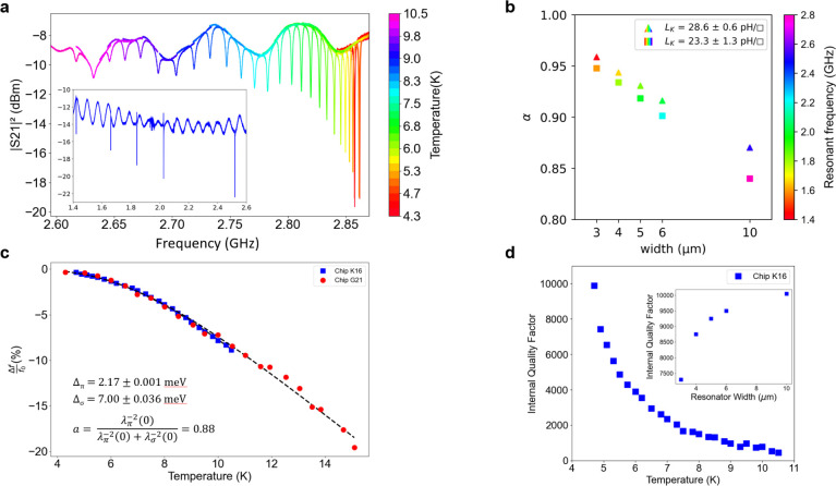
MgB2 RF device measurements. (a) S21 transmission of a MgB2 resonator at different temperatures. Inset shows the five resonances corresponding to a perfect yield on this chip. (b) Alpha (α)—fraction of total inductance that originates from the superconducting kinetic inductance—for two different chips (plotted in triangles and squares) at different CPW conductor widths. The resonant frequency for each measurement is represented by the color fill. (c) Fractional frequency shift as a function of the temperature for two different resonator chips. Higher temperature data were not possible due to the high coupling factor to the resonators. In the future, we plan to design some low coupling resonators for better measurements up to the critical temperature. The fit is a crude two-gap model used by Yang et al.30 The gap values were highly constrained in the model to show the participation of the larger gap (about 12%) even for the polycrystalline films. (d) Internal quality factor (Qi) as a function of temperature. We performed interface cleaning processes to achieve Qi ≥ 104 and expect it to improve further as we mature the fabrication process. Inset shows the reduction in Qi seen for different cpw geometry (plotted as the center conductor width for Z0 = 50 ohms).

