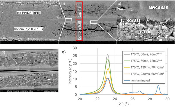
Figure 3.

SEM cross sectional images of hot laminated T‐PAPER samples. a) Detail of two laminated P(VDF‐TrFE) layers. b) Overview image showing both T‐PAPER halves. c) Detail of the interface paper coating/PEDOT:PSS/P(VDF‐TrFE). d) Insufficiently laminated P(VDF‐TrFE) layers. e) XRD diffractograms of P(VDF‐TrFE) layers laminated with different process parameters (cylinder temperature, treatment duration).
