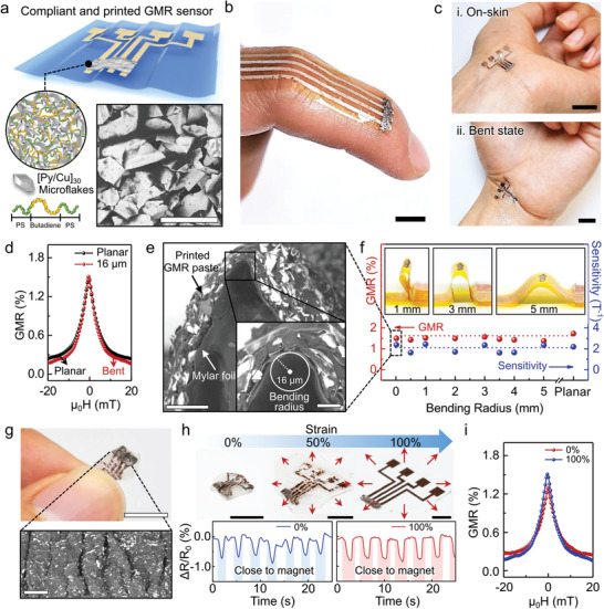
Figure 1.

Highly compliant and printed GMR sensors. a) Schematic illustration of GMR sensors consisting of [Py/Cu]30 microflakes and triblock copolymer (SBS) printed on ultrathin foils. SEM image reveals dried GMR paste printed on a Mylar foil. Scale bar: 100 µm. b,c) Photographs of printed GMR sensors conformably applied on skin with curved body parts of a finger (b) and a stretched (c‐i) and bent (c‐ii) wrist. Scale bar: 1 cm. d) GMR performance of the printed sensors under planar and bent state (16 µm of bending radius). e) Cross‐sectional SEM images of bent GMR sensors printed on an ultrathin Mylar foil. At the apex the GMR sensor is bent to the radius of 16 µm (inset). Scale bars: 100 µm, 20 µm (inset). f) The magnitude of the GMR effect and the sensor sensitivity following the gradual decrease of the bending radius from 5 mm to 16 µm. g) Photograph of the printed GMR sensor laminated to a VHB tape, which was initially biaxially prestretched to 100%. The photo shows the sensor in its relaxed state. Scale bar: 1 cm. The bottom panel in (g) shows an SEM image of the buckled surface of the sensor. Scale bar: 300 µm. h) Photograph of a stretchable printed GMR sensor from 100% of stretching to 0% of relaxed state. Bottom panel in (h), shows the time evolution of the variation of the normalized sensor resistance for the sensor in the relaxed state (0%) and after the sensor is stretched to (100%). The sensor is exposed to a field of a permanent magnet, which is manually approached and retracted from the sensor, which leads to the resistance change. Scale bar: 5 mm. i) GMR performance of the printed sensor in the relaxed (0% stretching) and stretched state (100% stretching).
