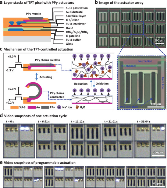
Figure 5.

Fabrication and actuation of the active‐matrix PPy actuator arrays. a) Schematic layout of the a‐IGZO TFT pixel with PPy actuators. b) Optical microscopy images of the PPy actuator array and a single pixel. The PPy actuator digits are connected to the drain of the TFT. c) Schematic illustration of the actuation mechanism. With the control TFT switched on, the PPy is in different redox states depending on the applied source bias, which leads to the absorbing and expelling of Na+ ions and water molecules. PPy muscles have a volume change and the digits are actuated. d) A series of video snapshots showing a 2 × 2 array with PPy actuators in one actuation cycle. e) Video snapshots of a 4 × 2 actuator array in different states during the programmable actuation.
