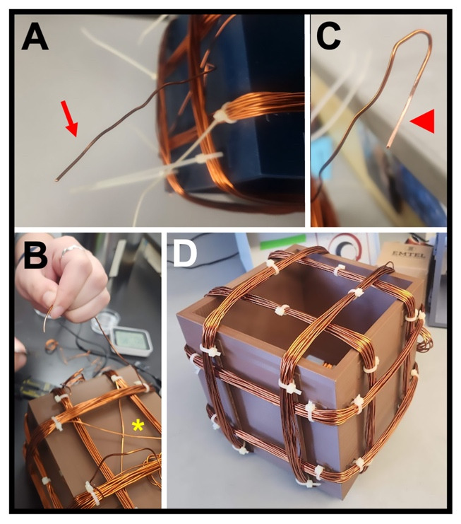
Figure 6. Winding the coils.

(A) Free end of the copper wire (arrow) for one coil, where 4 in (~10 cm) of wire is left unwound at each end for attaching to the power supply. (B) View of one face of a completed coil, showing the crossing of the copper wire (asterisk) between the left and right coil pairs. (C) Free end of one coil, showing the stripped insulation (arrowhead) required for a strong connection to the power supply lead. (D) Completed Helmholtz coil with three coil pairs (x, y, and z) that have been zip-tied (white clasps) to the base frame via the anchors and had the zip-tie “tails” cut off.
