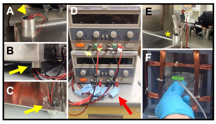
Figure 8. Connecting to the power source.

(A) Leads from a Helmholtz coil fed through an upper access port (arrowhead). (B–C) Views of a set of leads fed through a lower access port (yellow arrows), shown from the outside (B) and the inside (C) of the enclosure. (D) Power supplies with attached leads. Red arrow shows axis labeling of each lead. (E) Alligator clip end of ground lead (asterisk) attached to an upper port on the enclosure. (F) Probe end of a milli/Gaussmeter, taped to the stage in the correct orientation for that make of probe, during a test of field strength.
