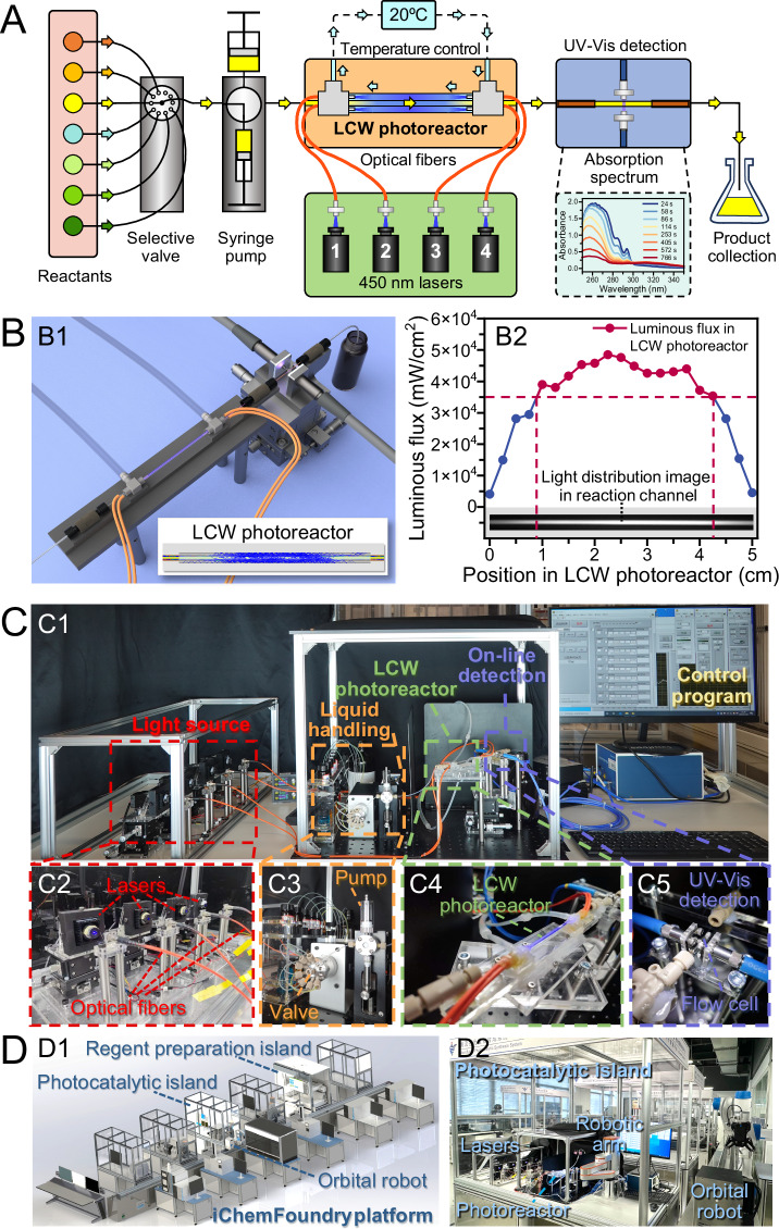
Fig. 1. Flow manifold and setup of the automated ultra-high throughput photocatalytic synthesis and screening system.
A Schematic diagram of the system flow manifold. B Structure and light distribution of the LCW photocatalytic microreactor. (B1) Schematic diagram of the LCW photocatalytic microreactor and online UV-Vis absorption spectroscopic detection device; (B2) Cross-sectional light intensity distribution in the reaction channel of the LCW photocatalytic microreactor obtained using TracePro software. C Photographs of the system. (C1) Overview of the system. (C2) Light source module, consisting of four 450-nm lasers and four optical fibers. (C3) Liquid handling module with a 10-port selective valve and a syringe pump. (C4) LCW photocatalytic microreactor. (C5) Online UV-Vis absorption spectroscopic detection module. D Schematic diagram (D1) and photograph (D2) of the iChemFoundry platform.

