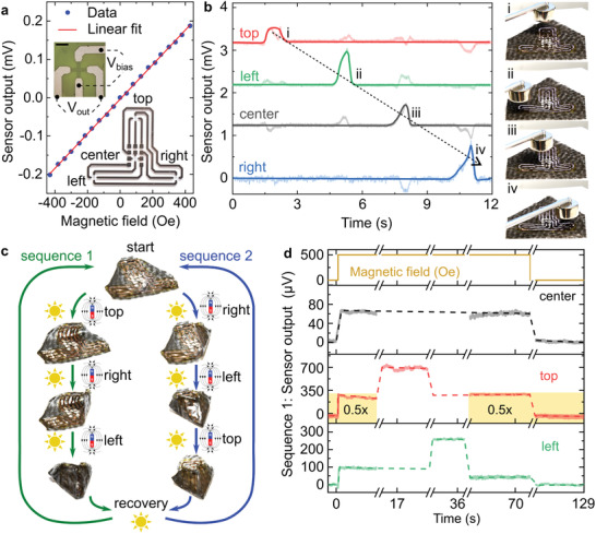
Figure 3.

Sequential folding monitored by compliant anomalous Hall effect sensors. a) Output voltage of a single compliant anomalous Hall effect sensor as a function of the magnetic field applied perpendicular to the sensor plane. The output of the sensor is read transversally to the bias voltage (upper inset, scale bar is 1 mm). Four sensors are connected in series, distributed on the foil support at the top, center, right, and left positions (lower inset). b) Time trace of the outputs of the sensors in response to a hovering permanent magnet. As the magnet is moved above the top (i), left (ii), center (iii), and right (iv) sensors, the voltage changes in the sensors detect its presence. c) Illustration of two actuation sequences for assembly of the magnetic origami without predefined hinges. From the initial state (start), selective illumination guides the actuator to fold first its top flap or not. Folding it last (sequence 2) achieves a more defined final state in contrast with sequence 1. Illumination in the absence of magnetic fields recovers the initial, planar state of the origami. d) Output of the anomalous Hall effect sensors and the externally applied magnetic field (uppermost panel) as a function of time. The sensor in the center (second panel from the top) serves as a reference and does not change after turning on the magnet. The left and top sensors (last two panels) present a specific output voltage before actuation, reach a new steady‐state voltage after folding, and then recover their initial state.
