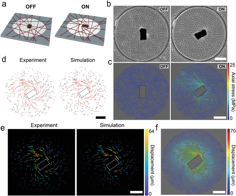
Figure 3.

Experimental and computational investigation of the actuation paradigm. a) As soon as the network is placed within the magnetic manipulation system, a torque clamp is activated for the µ‐actuator. Any deviation on the orientation of the µ‐actuator would generate a restoring magnetic torque. The orientation of the µ‐actuator is dynamically modulated to apply a local deformation to the fiber network. b) Phase‐contrast images showing the operation of the µ‐actuator. The magnetic field is rotated by 90° from the equilibrium configuration. c) A digital twin of the fiber network shown in (b) is manipulated to the same degree. The simulation results report the stress on the fibers along with the strain. d) The deformation is quantified by tracking fluorescent beads randomly distributed on the fiber network (left). The trajectories of points at the positions of the fluorescent beads are calculated by the computational model (right). e) The motion of the nodes introduced in (d) are displayed as a vector field for the experiment (left) and the digital twin (right). f) The displacement of all the nodes within the network are calculated using the digital twin. Scale bars: 100 µm.
