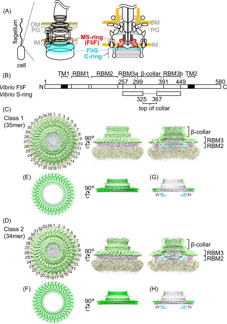
Fig 1.
Flagellar motor structure and MS-ring (FliF) in Vibrio. (A) Schematic diagram of the flagellar basal body in Vibrio. The Vibrio cell has a single flagellum at its cell pole, and there is a flagellar motor at the flagellar base. The MS-ring—consisting of FliF—and the upper part of the C-ring—consisting of FliG—are colored with red and cyan, respectively. OM: outer membrane, PG: peptidoglycan layer, IM: inner membrane. (B) Schematic representation of the Vibrio FliF primary structure containing the region forming the RBM1, RBM2, RBM3 (divided into RBM3a and RBM3b), β-collar, and transmembrane helices (TM1 and TM2) with residue numbers. The S-ring region built in the model in this study is shown in the lower part. (C and D) Surface representation and vertical section of the cryo-EM map of the purified MS-ring without rotational symmetry correction (C1) of Class 1 (35-mer) and Class 2 (34-mer). Green: S-ring, cyan: inner part of the M-ring, pink: middle part of the M-ring, yellow: unstructured outermost region of the M-ring, gray: unstructured innermost region. (E and F) The Cα ribbon drawings of the S-ring atomic models built from the maps after rotational symmetry correction (C35 for Class 1 and C34 for Class 2). (G and H) The Cα ribbon drawings of the S-ring atomic models with the previously reported structures of RBM2 (3).

