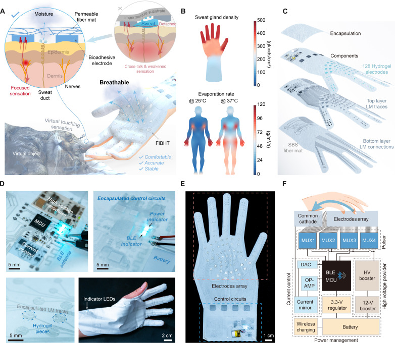
Fig. 1. Schematic illustration of the FIBHT system.
(A) Conceptual illustration of the features of the FIBHT system. (B) Sweat gland density distribution of the hand and sweat evaporation rate distribution on the human body (front) in situations of insensible perspiration (environment, 25°C) and heavy sweating (environment, 37°C). (C) Exploded view of the structure of FIBHT. (D) Optical image of details in the control circuits both before (left) and after (right) encapsulation. (E) Optical image of the complete FIBHT system. (F) Brief block diagram of the FIBHT system. DAC, digital-to-analog converter; OP-AMP, operational amplifier.

