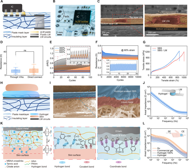
Fig. 2. Structures and materials of the system and interfaces.
(A) Schematic illustration of the cross-sectional view of the multilayer electronic circuits integration. (B) Optical image of the soldered chips and circuit details. (C) SEM images of the cross section of the LM VIA. (D) Resistance distribution of the LM traces to 128 electrodes, classified by connection through VIAs or direct connect. n = 62 for “through VIAs” group and 66 for “direct connect” group. ns, not significant (P > 0.05 in t test). (E) Resistance changes in extreme stretching test (300, 400, and 500% strain) of the LM trace. Thick line: curve envelopes. Inset: zoomed plot showing the initial 10 cycles. (F) Resistance changes in cycled stretching test of the LM trace (length, 5 mm; and width, 254 μm). Inset: zoomed plot showing the initial 30 cycles. (G) Stress-strain curves of pristine SBS mat and LM coated SBS. (H) Schematic illustration of the cross-sectional view of the skin/hydrogel/LM integration. (I) SEM images of the cross section of the hydrogel/LM interface on SBS fiber mat. (J) Areal impedances of the LM/hydrogel interface, with three sizes of hydrogel pieces. n = 9 (diameters of 2, 4, and 6 mm, three in each group). (K) Schematic illustration of the bonding in LM/hydrogel/skin interfaces and their equivalent circuit modal. MBAA, N,N′-methylenebisacrylamide; AAm, acrylamide; ZF, Faradic impedance; CDL, electric double layer capacitance; RH, hydrogel access resistance; RS, skin resistance; CSC, stratum corneum capacitance; EGaIn, eutectic gallium-indium. (L) Electrode-skin areal total impedances of bioadhesive hydrogel, 100% stretched hydrogel, commercial gel, and gold (Au) electrodes. n = 9 (diameters of 2, 4, and 6 mm, three in each group). SE, stimulating electrode; CE, counter electrode. For (E), (J), and (L), line: mean value. Error band: SD.

