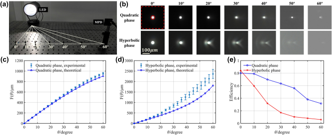
Figure 2:
Imaging performance comparison of the MPD and the hyperbolic phase metalens at different viewing angles. (a) Experimental setup for imaging of the LED while the imaging device is placed at different viewing angles. The viewing angles are marked below the position. (b) Quadratic phase and hyperbolic phase metalens imaging results corresponding to different incident viewing angles from 0° to 60°. The red circle and red square represent the focusing region and observed region, respectively. The measured and theoretical imaging positions of (c) quadratic phase metalens (the MPD) and (d) hyperbolic phase metalens at different viewing angles. The abscissa represents the LED viewing angles, while the ordinate (blue marked line & error bar) represents the distance from the imaging point to the CMOS center. (e) Focusing efficiency of quadratic phase and hyperbolic phase metalens at different viewing angles.

