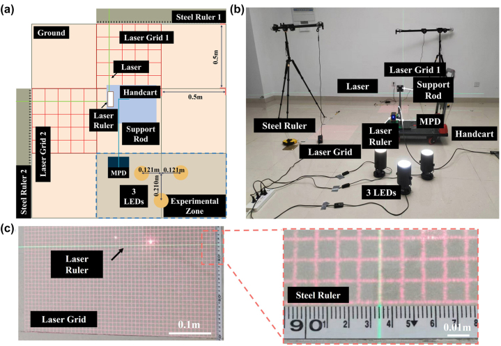
Figure 3:
Indoor positioning detection system. (a) Schematic diagram of the positioning solution and the related setups. (b) The physical diagram of the experimental setups and their indoor layout. (c) Schematic diagram for reference position reading, reducing reading errors by aligning the laser ruler with the laser grid.

