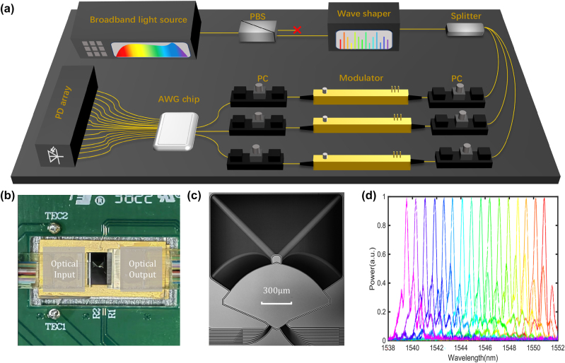
Figure 3:
Experimental realization of the convolver. (a) Experimental setup. PC, Polarization controller; PBS, Polarizing beam splitter; PD, photodetector. (b) Overall photo of the packaged layout. The integrated photonic core is mounted on a thermoelectric cooler (TEC). The optical input and output (I/O) are through the fiber arrays on the left and right sides. (c) Microscopic image of the fabricated AWG. (d) Measured transmission spectra of 16 output ports for corresponding one input port.

