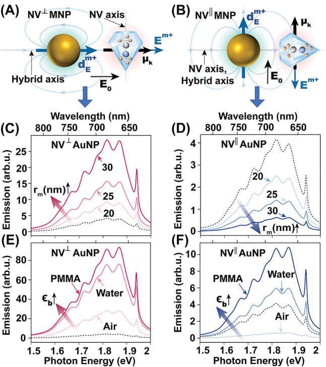
Figure 3:

Controlling NV emission using a plasmonic nanoparticle. (A) Schematic diagram of the NV⊥MNP setup where the external field is polarized along the hybrid axis and NV dipoles are perpendicular to the MNP surface. (B) NV‖MNP setup where the external field is polarized perpendicular to the hybrid axis and NV dipoles are parallel to the MNP surface. Subplots (C) and (D) show the variation of total near-field NV emission of the NV⊥AuNP and NV‖AuNP dimers in air for different MNP radii at R = 38 nm. Subplots (E) and (F) depict the submerging medium dependence for NV⊥MNP and NV‖MNP dimers with r m = 30 nm and R = 38 nm. Refractive index 1, 1.33, and 1.495 for air, water, and PMMA, respectively. Reference (dashed black) curves in subplots (C)–(F) show the isolated NV emission for the respective cases in air. All emission plots are normalized by the area of the respective reference curve.
