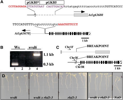
Figure 3.
wvd6 is caused by a translocation that disrupts RHD3. A, Structure of the wvd6 translocation. The top image represents the arrangement of DNA on the translocated chromosome carrying the chromosome 3 centromere, while the bottom image represents the DNA arrangement on the chromosome carrying the chromosome 1 centromere. The 5′ and 3′ untranslated regions of RHD3 are represented by striped boxes and the coding region of RHD3 by black boxes. Gray boxes are used to represent the predicted first exons of At1g63670 and At1g63680, with arrows indicating the direction of transcription. The gray lines and boxes correspond to DNA originating from chromosome 1, and the black lines and boxes correspond to DNA originating from chromosome 3. Note that the pGKB5 T-DNA inserts are not drawn to scale. The asterisk (*) denotes the truncated T-DNA. The sequences shown represent the various junctions between chromosome 1, chromosome 3, and pGKB5. Sequences in red bold correspond to RHD3 (chromosome 3); sequences in purple italics are from pGKB5; uppercase black sequences are from chromosome 1; and lowercase black sequences are of unknown origin. B, PCR-based confirmation of the wvd6 translocation. Wild-type Ws genomic DNA served as the template for the PCR reactions loaded in lanes 1 and 2, and wvd6 genomic DNA was used for lanes 3 and 4. The primer pair used for lanes 1 and 3 was Chr3F and Chr3R, while Chr1F and Chr3R were used for lanes 2 and 4 (see “Materials and Methods”). Their positions on wild-type chromosomes 1 (top) and 3 (bottom) are depicted by arrows in C, which also shows the translocation breakpoints in the wvd6 mutant. D, From left to right, root growth behavior of 7-d-old wvd6, wvd6 × rhd3-3 (F1), rhd3-3, wvd6 × rhd3-3 (F1), and wild-type No-0 seedlings grown on tilted hard-agar surfaces showing that wvd6 and rhd3-3 do not complement each other.

