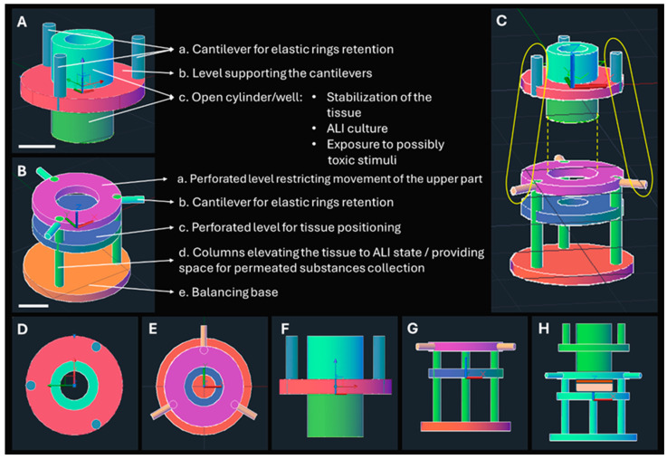
Figure 2.
CAD designs of the Epi-ExPer device. The upper (A) and lower (B) parts, with their compartments ((A). a–c and (B). a–e) and their roles, are described. Scale bars indicate 3 mm. The relevant position (C) of the upper and lower part, where the assembling direction is indicated with a yellow dashed line and the placement of the rubber bands is indicated with the yellow circles. The upper view of the upper (D) and lower (E) parts and the side views (F,G) are depicted. The assembled device with an animated epithelial tissue is illustrated (H).

