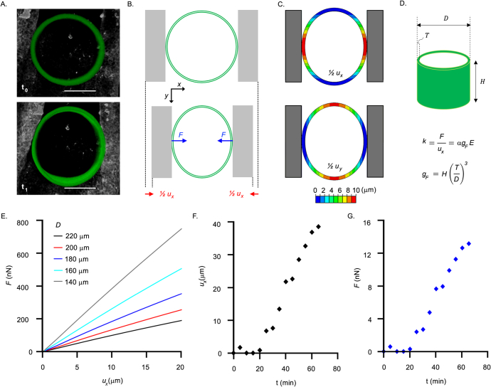
Extended Data Fig. 8. Development of Finite Elements Method (FEM) models and derivation of a parametrized equation to evaluate force from cylinder iMeSH shapes.
a. Dorsoventral view of an i3D cylinder incorporated within the neural folds of a representative chick embryo at different time points (t0 = 0, t1 = 65 min). Scale bar = 100 μm. b. Scheme showing the compressive force F on the cylinder walls, due to the growth and folding of the neural tube, and the corresponding deformation of the cylinder. In the reference system, x is the medial-lateral direction and y the cranio-caudal direction. c. Contours of absolute displacement in the medial-lateral direction (ux) and in the cranio-caudal direction (uy). The cylinder narrowing in the medial-lateral direction from experimental data is the input of numerical analysis, which allows to estimate the corresponding contact force. d. The cylinder stiffness k, as the ratio between the contact force F and the displacement ux, is proportional to the hydrogel Young’s modulus E and to a geometric factor gF, which depends on cylinder height H, diameter D and wall thickness T. The scalar α in the parametric equation is a fitting constant (α = 7.718). e. Contact force (F) versus displacement (ux) for cylinders with the same height (H = 100 mm), thickness (T = 25 mm) and elastic modulus (E = 80 kPa) and varying diameter D, from numerical analyses. f. Displacement (ux) versus time (t) measured in a i3D cylinder incorporated in a chick embryo at different time points in a representative experiment. g. Contact force values versus time estimated via the parametric equation using experimental displacement data as input.

