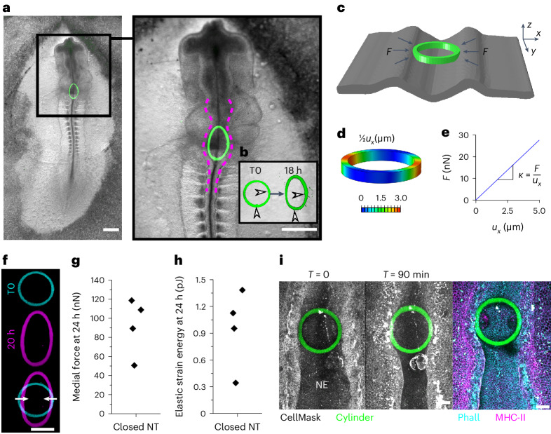
Fig. 3. Quantification of medial force applied by the closed neural tube.
a, Bright-field view of a chick embryo 18 h after an iMeSH cylinder (green) was bioprinted within its open neural tube. Dashed lines indicate the neural folds. Scale bars, 500 µm. b, Confocal 3D reconstructions of the cylinder in the same embryo following bioprinting (T0) and 18 h later. Arrowheads indicate small landmarks incorporated in the cylinder, demonstrating minimal rotation. c, FEM model of an iMeSH cylinder and surrounding tissue based on 3D reconstruction of the specific morphometry, with the representation of contact forces (F) between tissue and cylinder. In the reference system, x is the medial–lateral direction, y the craniocaudal direction and z the dorsoventral direction. d, Contours of absolute displacement in the mediolateral direction (ux). e, Resultant contact force versus narrowing in the mediolateral direction. The slope of the curve corresponds to the cylinder structural stiffness, k. f, Projected image of a cylinder printed in a chicken rhombocervical neuropore immediately after printing and in a deformed state within the lumen of the neural tube 20 h later. Scale bar, 100 µm. g,h, Quantification of medial force applied (g) and elastic energy stored within compressed cylinders (h) incorporated in a partially closed neural tube (NT), 24 h after printing. Points represent individual embryos. i, Representative embryo immediately after iMeSH printing and 90 minutes later to visualise the iMeSH cylinder. The same embryo was fixed and stained with the plasma membrane dye CellMask, phalloidin (Phall) to label F-actin, and immuno-labelled to detect myosin heavy chain (MHC)-II. NE, neuroepithelium; T, time; scale bars, 50 µm.

